


Reverse datum
Reference the complete attachment-side plane only after the actual reverse construction is confirmed.
Translate a dimensional logo into measurable planes instead of describing it as simply “more raised.” The request should identify a reverse datum, base profile, elevation hierarchy, edge transition and receiving-product clearance, while final values remain subject to the supplier drawing and physical sample.

A profile needs a consistent origin. Define whether measurements begin at the reverse surface, the face base plane or another supplier-confirmed reference, then show that zero line on every cross-section. Without a declared datum, two reviewers can describe the same ridge with different numbers and both appear correct.
Reference the complete attachment-side plane only after the actual reverse construction is confirmed.
Identify the shared visible base from which face elevations rise or recess.
Number secondary lettering, borders or icons separately from the body.
Mark the highest approved feature and its relationship to neighboring zones.
The phrase 3D TPU label thickness should therefore name the dimension being discussed: complete profile, base body or relative relief. Teebling can assess the intended hierarchy after the buyer submits a labeled section drawing.
Product 43 is 3D TPU Silicone Heat Transfer Labels, recorded as TPU silicone at 5 cm, MOQ 100 and code DG-ZK-002. Product 44 is TPU Heat Transfer Logo Labels for Clothing, recorded as TPU and silicone at 5 × 3 cm, MOQ 100 and code GZ-FC-003. Neither row publishes thickness, elevation, shore hardness or line-width limits.
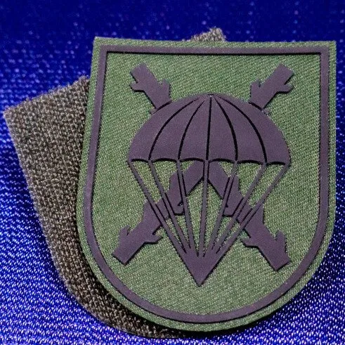
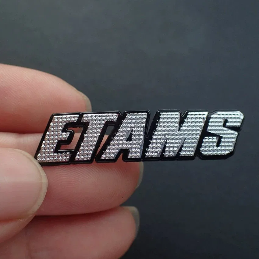
Compare Product 35, Product 43 and Product 44 under their separate identities.
Separate visual importance from physical height. A 3D TPU logo may use a quiet body, a raised brand name and a peak icon, yet the supplier must confirm which differences are feasible at the requested footprint. Number each band and state whether a transition is stepped, sloped, rounded or recessed.
Draw the complete body and intentional garment-visible openings without simulated shadows.
Assign the lettering or symbol that must remain visually dominant at normal viewing distance.
Use a separate callout for borders, small captions or decorative texture that cannot share the peak.
Distinguish a true recess from an unfilled opening, printed mark or color change.
Search language such as logo TPU 3D and TPU badges should be converted into this elevation legend before a quotation is compared.
Place a cut line through representative features and show what the section intersects. The drawing should state physical units, finished face width and height, overall profile from the confirmed reverse datum, and each relative elevation. If the component flexes or curves in use, add a separate product-context view rather than distorting the measurement diagram.
The relief artwork guide supplies file-layer controls; this page owns the dimensional vocabulary used on the section cut.
A dramatic enlarged render can hide closed counters, merged ridges and fragile transitions. Print the design at 100 percent scale, identify the smallest letter, narrowest channel, closest color boundary and tightest corner, then ask Teebling to mark any proposed simplification on a revision-controlled proof.
Keep interior openings legible after relief and edge treatment are applied.
Show the intended separation between adjacent raised regions.
Define where color changes coincide with or remain independent from elevation.
Call out pointed, rounded and internal corners that affect the visible silhouette.
State whether a tiny feature may be enlarged, flattened or removed only through approved revision.
A 3D raised rubber logo patch is a buyer-direction phrase, not evidence that the selected row uses rubber. Preserve Product 35's stored TPU wording when it is the cited reference.
Overall thickness cannot be approved until the reverse construction is identified. Request a labeled rear view and section that distinguishes the TPU body from any supplier-confirmed attachment layer, carrier or sewing allowance. Then place the proposed profile beside seams, pockets and folds on the intended receiving product.
Can equipment contact the complete reverse? Does the edge interfere with a nearby seam? Will a raised face sit beneath another garment layer? Is the component applied to a flat panel or assembled product? Which profile remains after any temporary carrier is removed?
The drawing should answer geometry questions; the physical trial should document how the exact label and garment behave under the current application direction. No pressure, temperature, dwell or peel sequence is supplied here.
Continue with TPU attachment planning and the label application trial after the profile is defined.
Agree on the measurement method before results are compared. Identify the point, instrument, orientation and whether soft compression can change the reading. Photograph the sample in profile with scale, record the artwork and construction code, and distinguish nominal supplier dimensions from observed sample measurements.
Match product, material wording, artwork revision, size and color proposal.
Use the same zero plane shown on the accepted cross-section.
Measure named base, relief and peak locations rather than convenient random spots.
Review the component flat and on the representative receiving product.
Record accept, revise or reject with the measured evidence and reviewer.
The TPU quote intake organizes commercial and variant fields around this technical evidence.
These answers protect the distinction between catalog size, overall component profile and relative face elevation.
There is no universal value on this page. Define the desired visual hierarchy, receiving product and attachment clearance, then obtain a dimensioned supplier drawing and measured sample for the selected construction.
No relief-height field is recorded for Products 35, 43 or 44. Their stored material, reference size, MOQ and item code can anchor an inquiry, while elevation values remain quotation and sample decisions.
Overall profile measures the complete component from reverse datum to highest face point. Raised detail describes the difference between named face zones, so both dimensions need separate callouts.
No. Shadows communicate appearance but not measurable geometry. Use numbered zones, a cross-section, physical units and a profile legend tied to the same artwork revision.
Check overall profile, relative zone heights, edge shape, fine-detail separation, color boundaries, reverse construction, flexibility in context and clearance on the actual receiving product.
Package authorized vector artwork, physical face dimensions, numbered elevation legend, cross-section, edge callouts, reverse request, receiving product, placement, quantities and sample milestone. Request that the returned quotation identify proposed materials, feasible profile dimensions, tolerances requiring agreement and the revision used for its calculation.
Release production only against the signed drawing and coded physical sample. If a logo, size or attachment route changes, advance the profile revision so an earlier thickness approval cannot be applied silently to a different build.